 biuro@elektrobim.pl
 91 817 14 69


What is it and how it works – the H-bridge
In the previous article that you can read here, I wrote that the so-called “H-bridge” is our favorite design and I promised to explain why ? In this article I meet the threat ? So I invite you to read these few words explaining what it is, how it works, how it can be built and what it can be used for – I present to you : “The H-bridge”
H-bridge – how it is built
A very simplified diagram of the H-bridge is shown in the figure below.
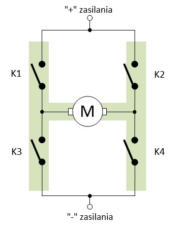
As you can see, the structure of the bridge is very simple: there are four connectors, one in each branch of the bridge. The bridge input is connected to a DC voltage source (e.g. battery, power supply, solar panel or whatever) and the output is connected to a load – in this case a DC motor (e.g. electric actuator). I have also incorporated a capital letter “H” into the diagram so that you can immediately see where the name of the system comes from :)
Only the two “diagonal” contacts of the bridge ( K1 and K4 or K2 and K3) or the contacts in the two upper or two lower branches of the bridge (K1 and K2 or K3 and K4) can be activated at the same time.
Do not allow a situation in which the contacts K1 and K3 or K2 and K4 will be activated at the same time, because this will cause a short circuit in the power line and may damage the power supply or connectors (or both).
H-bridge – principle of operation
Simply put, the H-bridge plays the role of a switch that allows you to change the voltage polarization at its output, so it enables, for example, to control the “right / left” DC motor.
I will present you four situations now:
1. K1 and K4 switches are closed (that is ON). K2 and K3 switches are open (switched OFF). The situation is shown in the figure below.
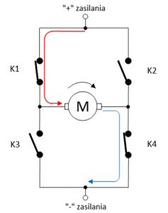
The left motor terminal via the K1 contact is connected to the power supply plus, and the right motor terminal via the K4 contact is connected to the supply minus. The direction and path of current flow from the positive to the motor is shown by the red arrow, and from the motor to the negative, the blue arrow. In such a situation, the motor will spin in one direction – let’s assume that it will spin to the right (as indicated by the black arrow in the figure).

2. Closed switches K2 and K3. K1 and K4 switches are open. The situation is shown in the figure below.
This time it is the other way around: the right end of the motor through the K2 contact is connected to the supply plus, and the left end of the motor through the K3 contact is connected to the supply minus. We can see that this time the current flows through the motor in the opposite direction as the last time. In this case, the engine will also rotate in the opposite direction – conventionally counterclockwise according to the black arrow in the figure.
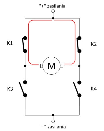
3. Closed switches K1 and K2. K3 and K4 switches are open.
Nothing happens in this situation ?
The motor will not rotate in either direction because both motor terminals are connected to a point of the same potential (positive supply voltage) via contacts K1 and K2, so the voltage at these terminals is zero.
4. Closed switches K3 and K4. K1 and K2 switches are open.
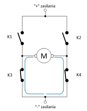
The situation is identical to the previous one, i.e. the engine does not work.
The only difference is that both motor power terminals are connected to the power supply negative. Still, it is a point with the same potential, so there is no tension on the motor to set it in motion.
Let me just remind you that in the H-bridge – for example, as shown in all the pictures above – the connectors K1 and K3 or K2 and K4 or all of them should not be turned on at once. This condition causes a short circuit between the positive and negative of the power supply. This can damage the power supply or switches (or both). The engine will definitely not turn in either side then :)
H-bridge – Controlling an electric actuator in practice
The practical implementation of the H-bridge can be done in many ways and using various types of switches – mechanical and electronic (bipolar or unipolar transistors – most often MOSFET).
Of course, you can use four manual connectors and build a dot-to-dot pattern as in the previous drawings ? However, this solution has disadvantages. First of all, you must remember not to turn on forbidden pairs of switches (i.e. K1 and K3 as well as K2 and K4) at once and not to cause a short circuit between the power points. In addition, to change the engine speed you have to switch (!!! in the right order !!!) as many as 4 switches! It can be complicated to use, and you will definitely admit that it is too easy to make a mistake ?
Therefore, I will show you below 4 easiest ways to implement such a bridge in practice, but without complicating your life too much ? We will leave uni- and bipolar transistors to electronics, and we will look at ways that can be implemented even by a person without any experience in craftsmanship :)
1. Double toggle switch
Build a layout as shown on the right.
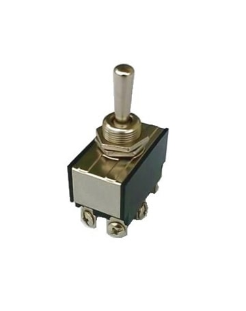
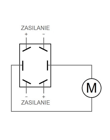
Electric actuator control direction switch electric actuator control direction switch diagram
The power supply is connected to the “corner” contacts, “crosswise”.
The output is the two middle contacts on which the voltage polarity changes. Such a switch has 3 positions: the two extreme ones provide voltage to the output in the “+/-” or “- / +” configuration, depending on the “lever” position. The middle position of the “lever” means no output voltage, so the actuator is then stopped.
The switch is available here.
2. Two-way switch
Build a layout as shown on the right.
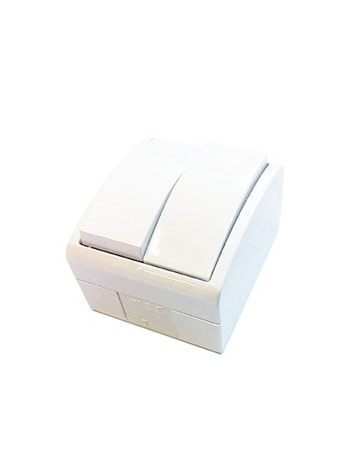
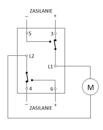
The switch has two keys, each of them connects one of the outputs (L1 or L2) to the positive or negative of the power supply.
Thus, it allows the motor to work in both directions, but also to stop it at any time – it is enough to set both buttons so that both outputs L1 and L2 are connected to the same power supply pole. The switch is available here.
3. Relay with double NC-COM-NO contacts (i.e. DPDT relay – two-circuit with a changeover contact
You can see the circuit connection diagram in the picture below. Looks familiar? If you’ve read the article about automatic chicken coop doors, it has to. :)
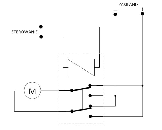
The input marked as “CONTROL” turns the relay on or off. The output contacts of the relay are connected in such a way that when it is turned off (no signal at the “CONTROL” input), there is a positive supply pole on one of the motor supply contacts, and a negative supply pole on the other. After activating the relay with the signal at the “CONTROL” input, the voltage polarity on the motor changes.
Such a system has the property that it does not de-energize the motor. The supply voltage is always supplied to the motor in one of the two polarities (- / + or +/-). If such a system is to be controlled by an electric actuator, it should have built-in limit switches cutting off the power supply from the motor so that it can turn itself off when it reaches an extreme position.
Another circuit that I want to show doesn’t have this “defect” :)
4. Two separate relays with single NC-COM-NO contacts (i.e. SPDT relays – single-circuit with a changeover contact)
Take a look at the diagram below. One relay with double contacts is replaced by two separate relays with a single changeover contact.
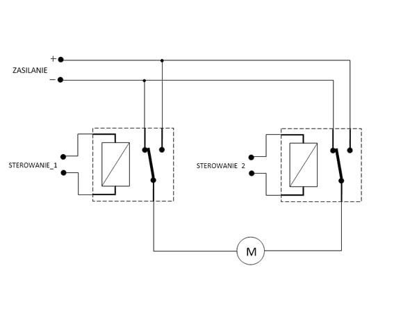
Such a connection makes it possible to independently control the relays through separate “CONTROL 1” and “CONTROL 2” inputs. Independent control of two relays allows not only to reverse the polarity of the voltage on the motor (either one or the other relay is on), but also allows the engine to be turned off by connecting both motor contacts to the plus or minus (both relays on or both off) – which is equivalent with power disconnected from the engine. 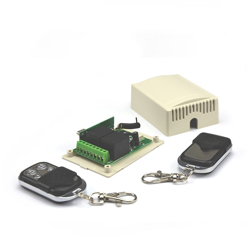
So, in the discussed example with two separate single relays, as in the previous one with one double relay, the control inputs can be given a signal from any source (e.g. an output of some digital control system, PLC controller, or something else). The basic condition is that the output voltage of the control source matches the supply voltage of the relay coil.
The circuit shown in the figure above can be implemented easily using our two-channel radio remote control.
Summary
I hope that I have made it a bit clearer for you about the structure and principle of operation of the H-bridge. And it turned out that “the devil is not as scary they say” ?
Of course, you can build systems with uni- or bipolar transistors, which, apart from just changing the polarity of the motor’s power supply, will also be able to control its speed, but these are more complicated creations. And I promised that this article will be simple, so I have to keep my word ?
As you can see, the H-bridge is a very useful contraption and makes it much easier to control electric actuators. What suits us best here is the fact that it enables the automation of control of such an actuator (I mean especially the last system with two relays).
That’s why it’s our favorite design! ?
Finally, you can also see how it looks in practice on our video about simple electric actuator control.


